Project
CAMpad
A custom programmable control pad built specifically for CAM programming in ESPRIT.
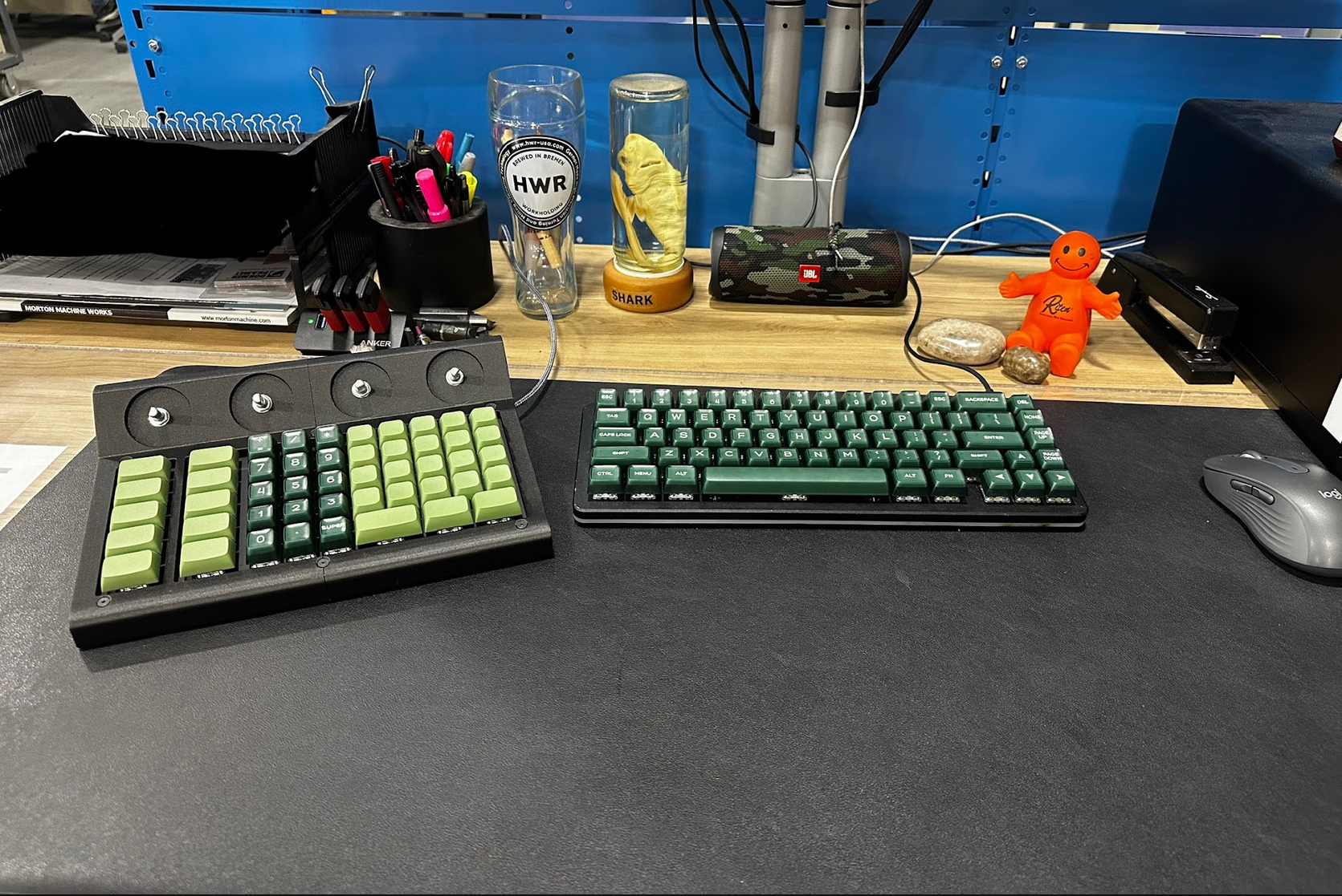
I designed CAMpad to put the commands I use most often directly under my left hand while keeping my right hand on the mouse. It combines keyboard shortcuts, CAM-specific macros, numeric entry, programmable layers, and model-view controls into one purpose-built desktop controller.
01 / Purpose
Why I built it
I originally built this device because I was frustrated with the shortcut options available in ESPRIT. Most commands could only be assigned to the F1-F12 keys, the numeric keypad, or combinations using modifier keys. I wanted frequently used commands to be available with a single button press and physically grouped together in a layout designed around the way I actually program parts.
I had also been interested in devices such as the Elgato Stream Deck and 3Dconnexion SpaceMouse. Rather than buying several separate devices, I decided to build something specifically for my own CAM workflow using concepts from mechanical keyboards.
Build details
- Overall size
- ~10 x 8 x 2.5 in
- Switches
- 48x Zealios V2 78 g
- Controller
- Raspberry Pi Pico / RP2040
- Encoders
- 4x EC11
- Firmware
- KMK
- Diodes
- 1N4148
- Switch plate
- 0.0595 in aluminum
- Enclosure
- Markforged Onyx
- Material cost
- ~$75
- Total time
- ~37-47 hours
02 / Controls
What it does
CAMpad contains 48 mechanical keys and four rotary encoders. Each rotary encoder provides clockwise rotation, counterclockwise rotation, and a push-button input, giving the four knobs twelve possible input actions in addition to the 48 keys.
Physical controls
- 5 general shortcut keys
- 5 modifier/control keys
- Full numeric keypad positioned for left-hand use
- 20 CAM macro keys
- 4 clickable rotary encoders
- Multiple programmable layers
CAM-specific macros
- Pocket, wall, chain, freeform, and hole features
- Facing, pocketing, contouring, and drilling operations
- Part, fixture, and tooling imports
- Measurement tools and simulation controls
- Other frequently used setup commands
Secondary layer / common decimal entry
A second programmable layer turns many of the keys into shortcuts for commonly used decimal values. This is useful when entering stock dimensions, tool dimensions, offsets, stepovers, and other values that repeatedly appear in machining.
.015625 / .03125 / .0625 / .09375 / .125 / .1875 / .250 / .375 / .500
The current CAMpad uses two primary layers, but the firmware can support additional layers as the layout evolves.
Rotary encoder / view controls
The four rotary encoders provide quick model-view controls without moving my hand away from the CAMpad.
| Encoder | Rotation | Press |
|---|---|---|
| 1 | Rotate about pitch | Snap to Top View |
| 2 | Rotate about yaw | Snap to Left View |
| 3 | Zoom in / out | Snap to Front View |
| 4 | Rotation currently unassigned | Snap to Isometric View |
Because the layout is software-defined, I can change any key, reassign encoder functions, or add additional layers as needed without modifying the hardware.
3D model
campad-assembly.glb
03 / Construction
Mechanical design and build
3D-printed enclosure
I modeled the complete CAMpad in SolidWorks. The finished device is approximately 10 x 8 x 2.5 inches and was designed around the the number and type of controls I wanted.
The enclosure was designed as a single part, but it was too large to fit the available 3D printer. I split the housing from front to back and used press-fit dowel pins to locate the two halves. The aluminum switch plate spans both halves and is fastened with 6-32 screws, helping lock the complete enclosure together once assembled.
CNC-machined aluminum switch plate
Instead of relying entirely on a printed structure, I designed an aluminum switch plate to support and accurately locate the mechanical switches. The plate is approximately 0.0595 in thick and was machined on a Hurco CNC mill using a program I created in ESPRIT. The plate provides a rigid, accurate mounting surface for the keys and mechanically ties the two printed enclosure halves together.
Electronics
The entire CAMpad is hand soldered. The 48 Zealios V2 78 g mechanical switches are wired into a row-and-column keyboard matrix using 1N4148 diodes, and the four EC11 rotary encoders are wired directly to the controller. I purchased Blank keycaps and added my own text to them with clear labels.
Why I used a Raspberry Pi Pico
I chose a Raspberry Pi Pico instead of the more commonly used Pro Micro because the CAMpad needed more available I/O for the size of the key matrix, the four rotary encoders, and the overall control layout. The RP2040-based Pico gave me enough GPIO to build the layout I wanted without redesigning the device around the limitations of the controller.
Why I used KMK
I used KMK because it provided straightforward RP2040 support for the Raspberry Pi Pico and is configured in Python. That made experimenting with custom macros, layers, and rotary-encoder functions relatively easy during development.
The controller exposes its filesystem as a USB storage drive, allowing the Python configuration and keymap to be edited directly without a separate firmware-flashing workflow or hardware changes.
04 / Development
Four design iterations
The finished CAMpad was the result of four major design iterations. The earlier versions were used to refine the overall size, key count, key spacing, layout, and controller selection before I committed to the final enclosure and switch plate.
Time and cost
Mechanical design was completed over roughly one week and represented about 10 hours of CAD work. Fabricating the parts took approximately 5 hours, assembly and hand wiring took about 12 hours, and creating the custom KMK layout and macros took approximately 10-20 hours.
| Task | Approximate time |
|---|---|
| Mechanical design | ~10 hours |
| Machining / fabrication | ~5 hours |
| Assembly and hand wiring | ~12 hours |
| Firmware / custom layout | ~10-20 hours |
| Total | ~37-47 hours |
The total material and component cost was roughly $75.
What I would change in the next version
Custom PCB
The current CAMpad is completely hand wired. A future version will ideally use a custom PCB, which would greatly clean up the internal assembly, reduce wiring time, and make additional units easier to build consistently.
SpaceMouse-style 3D control
I would also like to replace or supplement the rotary encoders with a SpaceMouse-style multi-axis controller. The encoders work for basic model manipulation, but a true multi-axis input would make rotating and positioning 3D parts much more natural while keeping the macro and numeric functionality of the CAMpad in the same device.